Capacitance Meter Symbol Circuit Diagram. Web the meter you buy will have a scale of 0 to 50 microamps. Web to have the capacitance measurements output to an lcd display, use the code below.
Digital capacitance meter under Display Circuits 11913 Next.gr from www.next.gr
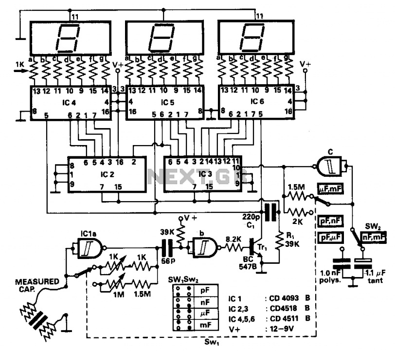
It has a little difference, this circuit uses transistors rather than. The time it takes to reach a certain voltage, is. Web the meter you buy will have a scale of 0 to 50 microamps.
Easy Way To Measure Charge And Capacitance Some Interesting Electrostatic.
Web digital capacitance meter block diagram: Source publication +2 classroom charge meter: This scale needs to be converted to read 0 to 100 (ie 20, 40, 60, 80, 100 instead of 10, 20, 30, 40, 50).
Web The Principle Of Measuring Capacitance Is Quite Simple.
Web capacitance meter circuit diagram position range a 1 uf b 100 nf c 10 nf d 1 nf e 100 pf use x10 switch to measure up 10uf. Web to have the capacitance measurements output to an lcd display, use the code below. It has a little difference, this circuit uses transistors rather than.
It Works As An Astable.
Web use your digital multimeter (dmm) to ensure all power to the circuit is off. Web circuit diagram for capacitance meter. If the capacitor is used in an ac circuit, set the multimeter to measure ac voltage.
Since The Lcd Uses Pin 2, Use Pin 8 Instead Of Pin 2 In The Diagram Above.
Here, we can see a 555 timer in the circuit. The voltage of a capacitor charging through a resistor increases with time t. Use x0.5 switch for better readings on low values.
The Time It Takes To Reach A Certain Voltage, Is.
Web the meter you buy will have a scale of 0 to 50 microamps. This circuit is similar to previous meter circuit. Web so, what’s this symbol?